By Mason Bloomfield
Last updated February 7, 2025
What is a Radar Sensor?
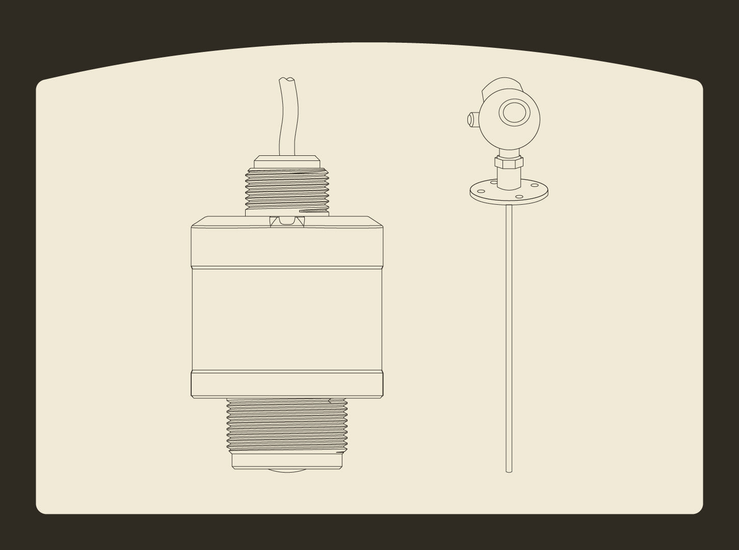
Radar sensors are among the most versatile and reliable level sensors on the market today, increasingly used in various applications within the water and wastewater industries. In this article, we will discuss three of the most common types of radar level sensors, how they work, and what they are used for.
What is a Radar Level Sensor?
Radar level sensors are continuous-level sensors that measure the distance between themselves and detected targets. They typically output a 4-20mA (milliamp) signal, which a controller interprets to determine the level reading. They are available in both non-contact and contact types and have a variety of configuration options ranging from different emission frequencies to specialized antenna attachments. Whether for general-use level monitoring or a specialized application, there’s a radar sensor to meet your needs.
Radar level sensors are commonly used in various industries to automate industrial processes, such as in wastewater management and the oil and gas industries. These sensors facilitate automation by monitoring the level of process media in the containment area and converting the measurement into an analog signal. Controllers can use this signal to turn pumps on and off, open and close valves, trigger alarms and notifications, and automate a variety of other industrial processes. Some examples include: water and wastewater level management, constant pressure boosting systems, oil and gas, chemicals and petrochemicals, food and beverage, and mining and minerals.

How Does a Radar Level Sensor Work?
There are several different types of radar level sensors on the market and all have slightly different operating principles. They all emit high-frequency microwaves, which are a form of electromagnetic waves, at a target and record how long it takes for the signal to travel to and reflect off of the target and return to the sensor. The sensor uses the elapsed time along with the signal speed to calculate the distance between the target and itself. Radar technology is robust, and the effects of most environmental conditions, such as temperature, steam, vapor, and wind on reading accuracy are negligible. Some extreme cases may have a minor impact on performance, but generally, radar technology can cope with such conditions. Radar level sensors are sensitive to the dielectric constant (K-value) of the media they measure and typically perform poorly when used with low K-value media. However, there are several ways that this sensitivity can be mitigated, such as the use of a specialized antenna or specific types of radar. For more information on radar-level sensing technology, see "An Overview of Radar Level Sensors and Ultrasonic Level Sensors: Which One Should I Use?"
Different Types of Radar Level Sensors
There are two main categories of radar level sensors: contact and non-contact. Each category has specific strengths and weaknesses while retaining the core advantages of radar technology.

Non-Contact Radar
Non-contact radar sensors are level sensors that can measure the level of a medium using radar beams without touching it. This is a significant advantage, making them easy to install. Since they don’t make contact with the process media they are easier to maintain and require less upkeep than other types of level sensors on the market. Two of the most common types of non-contact radar sensors are Pulsed Wave (PW) Radar and Frequency-Modulated Continuous Wave (FMCW) Radar.
Pulsed Wave Radar
Pulsed Wave (PW) Radar is the simplest and most common type of radar level sensor. It works by emitting short bursts of microwaves at the target, sampling the amplitude of the returning echoes to identify the level measurement, and then recording the time it takes for the waves to reflect off the target and return to the sensor. The radar will then calculate the distance between itself and the target by using distance measurement techniques, which involve multiplying the elapsed time and the speed of the signal (in this case, the speed of light) and then dividing the result by 2. This operating principle is known as the “Time of Flight” Principle (TOF).

PW Radars are known for their reliability, robustness, and accuracy. They are great all-around level sensors and can be used in almost any application. They are easy to install, require minimal maintenance, and are typically the most cost-effective type of radar level sensor on the market. Because they use radar technology, they are typically immune to factors such as high temperatures, steam, dust, moderate foam, residue buildup, and high pressure. That being said, this type of sensor is more susceptible to these conditions than the other types of radar sensors we will cover in this article. They are also more vulnerable to noise from false echos, which makes them less ideal for smaller, tighter spaces than other types of radar because they typically have a wider beam angle. This increases the likelihood of noise affecting the measurement due to clutter in the tank or the beam intersecting with the wall.

Frequency Modulated Continuous Wave Radar
Frequency-Modulated Continuous Wave (FMCW) Radar operates differently than PW Radar in that it emits a frequency-modulated continuous wave to measure distance. This means that instead of emitting short bursts of microwaves like a PW Radar, it continuously emits one long signal that changes in frequency over time. As a result, by the time the signal reflects off the target and returns to the sensor, it now has a different frequency or phase than the signal currently being emitted. The sensor measures the difference in phase or frequency between the emitted signal and the received signal. It then calculates the distance between the target and itself by multiplying the measured change in frequency by the speed of light and dividing the result by the rate of change in frequency per second multiplied by 2. In simple terms, the sensor compares the frequency of the emitted signal to that of the received signal to measure the distance. The difference in frequency is proportional to the distance between the sensor and the target.


The FMCW working principle offers many advantages compared to the TOF principle used by PW radar. As a result, FMCW radar level sensors have been increasing in popularity and are now one of the most commonly used radar sensors across many industries. Some of these advantages include:
-
a better signal-to-noise ratio (SNR)
-
higher accuracy
-
more resilience to challenging conditions such as changing temperature or pressure, heavy foam, and steam or vapor among others.
This type of sensor emits signals with greater energy than PW radar, allowing for better penetration power. Also, the FMCW method obtains distance by sampling echoes in the frequency domain (or FM range) and using the difference in frequency to indirectly measure the elapsed time from emission to reception of the signal. As we have discussed, PW radar directly measures the elapsed time, and samples echoes based on their amplitude (or in the AM range). Most noise sources in a tank are in the amplitude domain, meaning that FMCW radar is much less susceptible to noise factors from the tank, resulting in a higher SNR, or higher accuracy and resolution in the level measurement. FMCW radar is more sophisticated than PW radar and usually comes at a higher price point.

Contact Radar
Contact Radar sensors, as the name implies, require contact with the medium they are attempting to monitor. The most common type of contact radar is Guided Wave Radar (GWR), a relatively newer technology that has been steadily gaining popularity across various industries.

Guided Wave Radar
GWR is a contact variant of radar sensors. It consists of a radar transmitter with an attached guide probe. The guide probe extends down into the process media and guides the emitted signals to it. Its working principle is known as “Time Domain Reflectometry” (TDR), which was originally used to measure the length of cables and the location of cable interruptions and has since been adapted to radar level sensing technology. It works very similarly to the TOF principle. The sensor emits a signal along the guide probe. The signal travels down the probe and reflects back up the probe to the sensor upon encountering the process media. The sensor records the elapsed time between emission and reception of the signal and multiplies that by the speed of light divided by 2. The main difference between TDR and TOF is that the signal travels along the guide probe rather than through the air.

GWR technology comes with several advantages over its non-contact counterparts which is mostly due to the use of a guide probe to guide the pulse from the sensor to the process media and back. This process essentially eliminates external noise sources that could affect accuracy, making GWR especially suited for tight or narrow spaces and cluttered containment areas, as noise from physical obstacles and walls is of no concern. The guide probe also gives GWR the unique ability to measure and detect liquid interfaces. An example is the location and depth of the interface between oil and water. Another advantage the guide probe gives to GWR is the ability to reliably measure material with lower K-values (usually around ~>=1.4, where other types are typically limited to ~>=2.5) than other types of radar level sensors, which makes GWR a popular choice in the oil and gas industries.

Contact level sensors are usually associated with the drawback that since they come into contact with the process media, they are susceptible to build-up and thus require more maintenance. GWRs are unique among contact sensors because they can mitigate this issue. As long as the amplitude of the signal from the process media is larger than the amplitude of the noise from any residue build-up, the sensor can differentiate between the actual level and the noise and retain its accuracy reading. However, if it is used with low K-value media it may require cleaning to preserve accurate level measurements. Some other drawbacks of GWRs include limited range since their maximum range is limited by the length of the guide probe, a somewhat complicated installation process, the possibility of physical damage or corrosion of the guide probe due to process variables, and a higher price point on the market compared to other types of level sensors.
Considerations When Choosing a Radar Level Sensor
Process Media
Process media is a critical consideration when choosing a radar level sensor, as the dielectric constant (K-value) of the media is a key factor in determining sensor performance. Process media with a high K-value (such as water, which has a K-value of ~80) is great for use with radar because they reflect microwaves extremely well, which helps to increase measurement accuracy and reliability. Conversely, process media with a low K-value (such as many types of oils, most of which have a K-value of around ~2.1 - 2.4) will greatly undermine radar measurement accuracy and performance, and thus may not be suitable for most sensors or may require specialized measurement methods or sensor configurations. One popular solution is to use GWRs with lower K-value media since they can more reliably measure such material. (Click here for a reference list of K-values for common materials).
Sensor Positioning
Another very important consideration to make if you are planning on using a radar level sensor with your application is the sensor installation position within the measurement area. This can be broken down into several further considerations to make:
Tank Geometry
The geometry of the tank or measurement area is important to take into account when installing a radar sensor, especially for non-contact types. Some tank types, such as cylindrical tanks or tanks with domed tops, can cause a lot of signal interference due to signals reflecting off of the walls and back to the sensor, which will harm the performance of the radar. For example, it is best to install a non-contact radar on the shoulder of a domed roof and not in the center to avoid unwanted echoes. Placing your sensor off-center is a good rule of thumb for many tank types, but not all. Be sure to verify the ideal placement for your sensor depending on the measurement area for the best results!
Obstructions
Obstructions in the measurement area are also important to consider. Install your radar level sensor with a direct, unobstructed line of sight to the process media. Install the sensor away from inlet pipes, ladders, agitators, beams, and anything that can physically obstruct the signal or cause significant turbulence in the process media.

Blind Area
Radar sensors have a built-in blind area (or dead zone) to avoid immediate reflections from extremely close-range objects, which confuse the sensor. This means that the sensor will ignore anything within its blind area, so be sure to install the sensor at a height where the fill height of the containment area is below the blind area.
Beam Angle
The beam angle is the width of the radar beam of emitted signals from non-contact radar sensors. The beam angle is typically wider for lower-frequency radar and narrower for higher-frequency radar. The beam angle is important to consider when installing a radar level sensor because if the sensor is too close to the wall or any other obstacle, the beam will intersect with it and cause interference in the level reading. This is especially important in tall, narrow containment areas where even narrower beam angles may intersect with the wall as they propagate outward.

Application Variables
While radar technology itself is robust and mostly unaffected by the majority of environmental conditions and application variables, they should not be overlooked. It is important to verify that the sensor housing is rated for the pressure and temperature conditions present in the containment area and to choose a corrosion-resistant sensor if it will be used with corrosive media, as well as any other application variable present.
Other Considerations
If your application has extreme conditions or obstacles in the tank that are unavoidable, it may be beneficial to consider using a radar antenna. There are many varieties, and all are specialized for different situations. Some, such as a parabolic antenna, help to focus the beam angle and increase signal strength and range. Others, like a rod antenna, are very compact and suitable for tight spaces. Radar level sensor antennas can be used to specialize your sensor to your unique application.

Another option is to use a stilling well or a waveguide. These can be used to provide a clear path for the beam and reduce the impact of internal structures or tank geometry on the accuracy of the level measurement reading. They are also useful in applications with an excessive amount of foam or turbulence, as they can keep the area directly under the radar sensor calmer and clear of foam to increase the reliability and accuracy of the level reading.
Conclusion
Radar level sensors are some of the most commonly used level sensors across industries worldwide. They come in non-contact and contact varieties, each with specific strengths and weaknesses. Three common types are Pulsed Wave Radar, Frequency-Modulated Continuous Wave Radar, and Guided Wave Radar. PW Radars are simple and cost-effective and are a great all-around fit for many applications. FMCW Radars are more sophisticated, and their working principle allows them to achieve a higher SNR making them more reliable and accurate. They are a good fit for both straightforward level measurement applications as well as more challenging applications. Both PW and FMCW Radars are non-contact, making them easy to install and maintain. GW Radars are contact variant radar level sensors, which help minimize noise and allow them to work more reliably with low K-value media, making them well-suited for challenging applications.
There are many important considerations to make when choosing a radar sensor for your application, such as the process media, sensor positioning, application variables, specialization methods like different antenna options or using a stilling well, as well as choosing the right type of sensor based on its strengths and weaknesses. Paying close attention to these considerations will help you know which sensor to choose and will help ensure your radar sensor functions properly and reliably in your application.
References
-
"Frequency-Modulated Continuous-Wave Radar (FMCW Radar)," radartutorial.eu, accessed August 12, 2024
-
"FMCW vs. Pulse Radar: What is the Difference Between Frequently-Modulated Continuous-Wave (FMCW) and Pulsed Wave or Pulsed Width Radar?" Hawk Measurement Systems, accessed August 12, 2024
-
"Frequency Modulated Continuous Wave Technology: Improving Radar Accuracy and Reliability in Challenging Applications", Emerson, accessed August 12, 2024
-
"The Principles of Level Measurement," Fierce Electronics, October 1, 2000
-
"Radar Gauge Considerations," By A. Rahimi, Control Global, July 7, 2020


Share:
Promoting Your Local Business Online: A Guide for Plumbers and Contractors
Using IIoT in the Pump Industry